Ethernet Shield Web Server
Host a simple HTML page that displays analog sensor values.
In this example, you will use your Ethernet Shield and your Arduino board to create a simple Web server. Using the Ethernet library, your device will be able to answer a HTTP request with your Ethernet shield. After opening a browser and navigating to your Ethernet shield's IP address, your Arduino will respond with just enough HTML for a browser to display the input values from all six analog pins.
Hardware Required
Arduino Board
Circuit
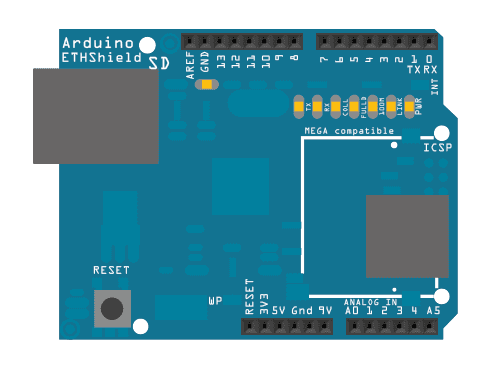
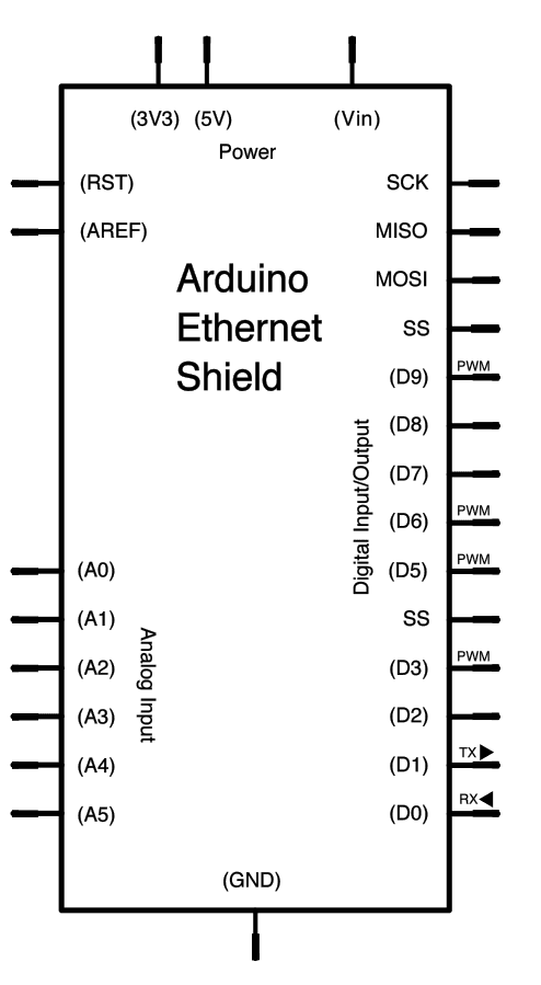
The Ethernet shield allows you to connect a WIZNet Ethernet controller to the Arduino boards via the SPI bus. It uses the ICSP header pins and pin 10 as chip select for the SPI connection to the Ethernet controller chip. Later models of the Ethernet shield also have an SD Card on board. Digital pin 4 is used to control the chip select pin on the SD card.
The shield should be connected to a network with an Ethernet cable. You will need to change the network settings in the program to correspond to your network.

Image developed using Fritzing. For more circuit examples, see the Fritzing project page
In the above image, the Arduino board would be stacked below the Ethernet shield.
Schematic

Warning
This example doesn't require an SD card. If an SD card is inserted but not used, it is possible for the sketch to hang, because pin 4 is used as SS (active low) of the SD and when not used it is configured as INPUT by default. Two possible solutions:
remove the SD card;
add these lines of code in the setup()
1pinMode(4, OUTPUT);2digitalWrite(4, HIGH);Code
Last revision 2018/09/07 by SM
Suggest changes
The content on docs.arduino.cc is facilitated through a public GitHub repository. If you see anything wrong, you can edit this page here.
License
The Arduino documentation is licensed under the Creative Commons Attribution-Share Alike 4.0 license.