Nano 33 BLE Rev2 Cheat Sheet
Learn how to set up the Nano 33 BLE Rev2, get a quick overview of the components, information regarding pins and how to use different Serial (SPI, I2C, UART) and Wireless (Wi-Fi®, Bluetooth®) protocols.
This article is a collection of guides, API calls, libraries and tutorials that can help you get started with the Nano 33 BLE Rev2 board.
You can also visit the documentation platform for the Nano 33 BLE Rev2.
Core
The Nano 33 BLE Rev2 uses the Arduino Mbed OS Nano Boards core.
Datasheet
The full datasheet is available as a downloadable PDF from the link below:
Installation
Arduino IDE 1.8.X
The Nano 33 BLE Rev2 can be programmed through the Classic Arduino IDE 1.8.X. To install your board, you can check out the guide below:
Arduino IDE 2
The Nano 33 BLE Rev2 can be programmed through the Arduino IDE 2. To install your board, you can check out the guide below:
Web Editor
The Nano 33 BLE Rev2 can be programmed through the Web Editor. To get started with your board, you will only need to install a plugin, which is explained in the guide below:
Using OpenMV IDE
If you want to use your board with MicroPython and OpenMV, follow the tutorial below:
If you want an overlook of the functions and features that MicroPython provides, take a look at the tutorial below:
Forcing Bootloader
There is a risk that the uploading process gets stuck during an upload. If this happens, double-tap the reset button, to forcefully trigger the bootloader.
Pins

Analog Pins
The Nano 33 BLE Rev2 has eight analog pins, that can be used through the
analogRead()1value = analogRead(pin, value);Please note: pins
and A4
should be used for I2C only.A5
PWM Pins
Pins D2-D12 and A0-A7 support PWM (Pulse Width Modulation).
Pins A4, A5 and D11, D12 are not recommended for PWM as they have I2C & SPI buses attached.
1analogWrite(pin, value);Digital Pins
There are a total of 14 digital pins.
To use them, we first need to define them inside the
void setup()1pinMode(pin, INPUT); //configured as an input2pinMode(pin, OUTPUT); //configured as an output3pinMode(pin, INPUT_PULLUP); //uses the internal 10k ohm resistorTo read the state of a digital pin:
1state = digitalRead(pin);To write a state to a digital pin:
1digitalWrite(pin, HIGH);5V Pin
The microcontroller on the Nano 33 BLE Rev2 runs at 3.3 V, which means that you must never apply more than 3.3 V to its Digital and Analog pins. Care must be taken when connecting sensors and actuators to ensure that this limit of 3.3 V is never exceeded. Connecting higher voltage signals, like the 5 V commonly used with the other Arduino boards, will damage the Nano 33 BLE Rev2.
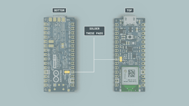
To avoid such risk with existing projects, where you should be able to pull out a Nano and replace it with the Nano 33 BLE Rev2, we have the 5V pin on the header, positioned between RST and A7 that is not connected as the default factory setting. This means that if you have a design that takes 5 V from that pin, it won't work immediately, as a precaution we put in place to draw your attention to the 3.3 V compliance on digital and analog inputs.
5 V on that pin is available only when two conditions are met: you make a solder bridge on the two pads marked as VUSB and you power the Nano 33 BLE Rev2 through the USB port. There are two sets of VUSB pads on the Nano 33 BLE Rev2, one set on the bottom and one set on top. To enable the 5V pin, either one of these needs to be connected If you power the board from the VIN pin, you won't get any regulated 5 V and therefore even if you do the solder bridge, nothing will come out of that 5V pin. The 3.3V, on the other hand, is always available and supports enough current to drive your sensors. Please make your designs so that sensors and actuators are driven with 3.3 V and work with 3.3 V digital IO levels. 5 V is now an option for many modules and 3.3 V is becoming the standard voltage for electronic ICs.

IMU

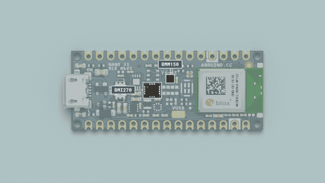
BMI270 and BMM150
The Nano 33 BLE Rev2 Inertial Measurement Unit system is made up of two separate IMUs, a 6-axis BMI270 and a 3-axis BMM150, effectively giving you a 9-axis IMU system. This allows you to detect orientation, motion, or vibrations in your project.
BMI270 and BMM150 Library
To access the data from the IMU system, we need to install the BMI270_BMM150 library, which comes with examples that can be used directly with the Nano 33 BLE Rev2.
It can be installed directly from the library manager through the IDE of your choice. To use it, we need to include it at the top of the sketch:
1#include "Arduino_BMI270_BMM150.h"And to initialize the library, we can use the following command inside
void setup()1if (!IMU.begin()) {2 Serial.println("Failed to initialize IMU!");3 while (1);4 }Accelerometer
The accelerometer data can be accessed through the following commands:
1float x, y, z;2
3 if (IMU.accelerationAvailable()) {4 IMU.readAcceleration(x, y, z);5 }Gyroscope
The gyroscope data can be accessed through the following commands:
1float x, y, z;2
3 if (IMU.gyroscopeAvailable()) {4 IMU.readGyroscope(x, y, z);5 }Magnetometer
The magnetometer data can be accessed through the following commands:
1float x, y, z;2
3 IMU.readMagneticField(x, y, z);Tutorials
If you want to learn more about how to use the IMU, please check out the tutorials below:
- Accessing IMU gyroscope data with Nano 33 BLE Rev2
- Accessing IMU accelerometer data with Nano 33 BLE Rev2
- Accessing IMU magnetometer data with Nano 33 BLE Rev2
Communication
Like other Arduino® products, the Nano 33 BLE Rev2 features dedicated pins for different protocols.
SPI
The pins used for SPI (Serial Peripheral Interface) on the Nano 33 BLE Rev2 are the following:
- (CIPO) - D12
- (COPI) - D11
- (SCK) - D13
- (CS/SS) - Any GPIO
The signal names MOSI, MISO and SS have been replaced by COPI (Controller Out, Peripheral In), CIPO (Controller In, Peripheral Out) and CS (Chip Select).
To use SPI, we first need to include the SPI library.
1#include <SPI.h>Inside
void setup()1SPI.begin();And to write to the device:
1digitalWrite(chipSelectPin, LOW); //pull down the CS pin2 3 SPI.transfer(address); // address for device, for example 0x004 SPI.transfer(value); // value to write5
6 digitalWrite(chipSelectPin, HIGH); // pull up the CS pinI2C
The pins used for I2C (Inter-Integrated Circuit) on the Nano 33 BLE Rev2 are the following:
- (SDA) - A4
- (SCL) - A5
To use I2C, we can use the Wire library, which we need to include at the top of our sketch.
1#include <Wire.h>Inside
void setup()1Wire.begin();And to write something to a device connected via I2C, we can use the following commands:
1Wire.beginTransmission(1); //begin transmit to device 12 Wire.write(byte(0x00)); //send instruction byte 3 Wire.write(val); //send a value4 Wire.endTransmission(); //stop transmitUART
The pins used for UART (Universal asynchronous receiver-transmitter) are the following:
- (Rx) - D0
- (Tx) - D1
To send and receive data through UART, we will first need to set the baud rate inside
void setup()1Serial1.begin(9600);To read incoming data, we can use a
while loop()1while(Serial1.available()){2 delay(2);3 char c = Serial1.read();4 incoming += c;5 }And to write something, we can use the following command:
1Serial1.write("Hello world!");Connectivity
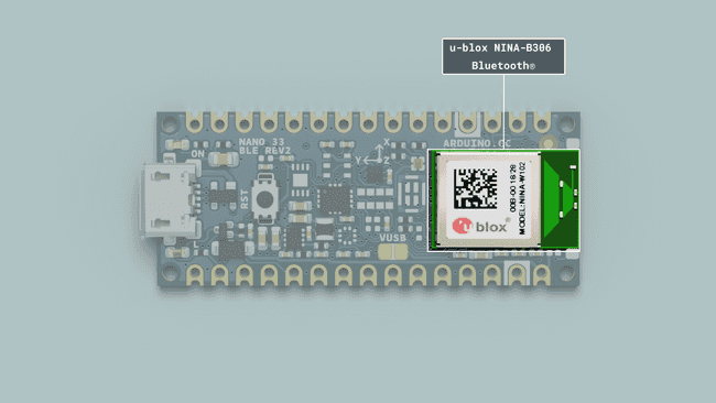
The Nano 33 BLE Rev2 supports Bluetooth® through the u-blox NINA-B306 module. To use this module, we can use the ArduinoBLE library.

Bluetooth®
To enable Bluetooth® on the Nano 33 BLE Rev2, we can use the ArduinoBLE library, and include it at the top of our sketch:
1#include <ArduinoBLE.h>Set the service and characteristics:
1BLEService ledService("180A"); // BLE LED Service2BLEByteCharacteristic switchCharacteristic("2A57", BLERead | BLEWrite);Set advertised name and service:
1BLE.setLocalName("Nano 33 BLE Rev2");2 BLE.setAdvertisedService(ledService);Start advertising:
1BLE.advertise();Listen for Bluetooth® Low Energy peripherals to connect:
1BLEDevice central = BLE.central();Tutorials
USB Keyboard
To use the board as a keyboard, you can refer to the USB HID library that can be found inside the core.
You first need to include the libraries and create an object:
1#include "PluggableUSBHID.h"2#include "USBKeyboard.h"3
4USBKeyboard Keyboard;Then use the following command to write something:
1Keyboard.printf("This is Nano 33 speaking!");Suggest changes
The content on docs.arduino.cc is facilitated through a public GitHub repository. If you see anything wrong, you can edit this page here.
License
The Arduino documentation is licensed under the Creative Commons Attribution-Share Alike 4.0 license.