Controlling LED over Wi-Fi Using Simulink with Nano 33 IoT
Learn how to control the Nano 33 IoT LED over USB and Wi-Fi with Simulink.
Introduction
In this tutorial, we will use Simulink to turn on the board's built-in LED over Wi-FI, made possible by the NINA module embedded on the Nano 33 IoT board and Simulink® Support Package for Arduino® Hardware.
Goals
The goals of this project are:
- Control the Arduino Nano 33 IoT LED with Simulink over USB.
- Control the Arduino Nano 33 IoT LED with Simulink over Wi-Fi.
- Understand the difference between various deployment methods.
- Create a dashboard to tune the PWM of the LED.
Hardware & Software Needed
- Arduino Nano 33 IoT
- Arduino Nano Motor Carrier
- Micro USB Cable
- Single cell LiPo/Li-ion 18650 battery and holder with XT30 connector
- Valid MATLAB® and Simulink® license
- Simulink® Support Package for Arduino® Hardware
The Arduino Nano 33 IoT, Nano Motor Carrier, Micro USB cable and single cell battery are included as part of the Arduino Engineering Kit Rev 2
A valid MATLAB® and Simulink® license is needed. Your workplace or education institution may have a subscription. Alternatively, a one-year trial subscription to MATLAB® is included as part of the Arduino Engineering Kit Rev 2.
What Is Model-Based Design?
Intelligent systems are driving society forward through mega-trends such as machine intelligence, digital twins, electrification and self-driving vehicles. As technology progresses, they become more challenging to handle and new approaches need to be explored to engineer them. Take for example a car. In the past, a simple ECU handled very basic functionality of the car. Today's self-driving cars can compose over 250 million lines of code handling an interconnected system of propulsion, navigation, safety and self-diagnostics.
A key note, is that all of these subsystems need to be aligned in tandem for the successful implementation of the final product. The solution is to apply Model-Based Design (MBD) where system models are used to better understand the process. Designing with Model-Based Design allows for fast testing of new ideas, exposure of design problems early in the design process, automation of code generation and acceleration of the design process. Model-Based design is the gateway to agile prototyping and test driven design, helping you deliver potentially shippable products rapidly and easily.
Why Simulink?
The start of MBD begins with a model. Simulink allows for an easy development of a model encompassing the system specifications, that enables collaboration within engineering subdisciplines, required for the product development. In other words, a wide range of pre-built blocks so you can build your model on the shoulders of academic and industrial giants.
As part of the Arduino Engineering Kit Rev2, Arduino has collaborated with Simulink to provide a unique and easy point of entry to advanced model based design building, upon the Nano Motor Carrier and the Nano 33 IoT. You now have access to all functionalities of the Nano Motor Carrier, directly within Simulink, for developing state-of-the art control algorithms leveraging the combined expertise of MathWorks and Arduino!
A tightly integrated hardware and software solution allows you to design and prototype quickly, identify issues before they rise and seek venues for optimization. Simulink and Arduino work together to provide a powerful model-based design tool, with minimal knowledge requirements yet impressive capabilities. In line with this, various operation modes are provided for communicating between the Arduino board and Simulink as part of Model-Based Design.
This tutorial is meant as a very basic introduction to using Simulink with the Nano Motor Carrier. For a detailed hands-on guide, including three exciting projects check out the Arduino Engineering Kit Rev 2 which also includes a 1 year trial of Simulink.
Operation Modes
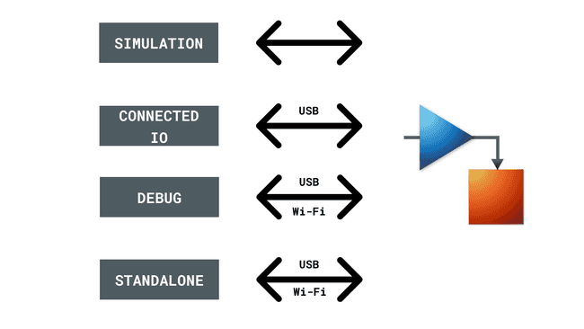
In line with the various stages of Model-Based Design, there are four ways to operate Simulink with Arduino hardware.
- Simulate operating condition in Simulink: Simulink allows you to run your algorithm in your computer without the hardware. This is very useful when testing out new flows quickly and rapidly using software models. This is also useful for testing without needing physical prototypes.
- Use the Arduino as a DAQ extension via Connected I/O: The Arduino hardware can be used as a data acquisition device or DAQ. The Arduino board only serves to provide input and output interfaces that can be connected to sensors and actuators respectively. The model that you see in Simulink however, is run completely on your computer.
- Deploy code for the Arduino model to run standalone: In this case, in addition to the I/O interface,the Arduino will run the blocks that Simulink has converted into machine readable code.
- External mode (monitor and tune): Simulink provides an option to change the operating parameters on the fly. This is useful for debugging, understanding how your Simulink model works in a real world environment as well as tuning of PID or other control systems.
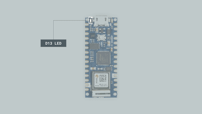
LED on the Arduino Nano 33 IoT
The LED in the Arduino Nano 33 IoT is connected to Digital Pin 13. By pulling this pin HIGH, we can turn the LED on and by pulling it LOW we can turn the LED off.
It is recommended that you go through the MATLAB tutorial before attempting this tutorial.
Simulate an LED Turning on and Off
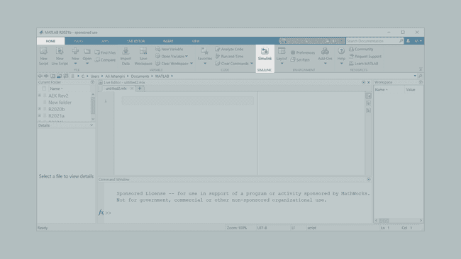
1. Open MATLAB. Under the Home ribbon, click on the Simulink button to open it.
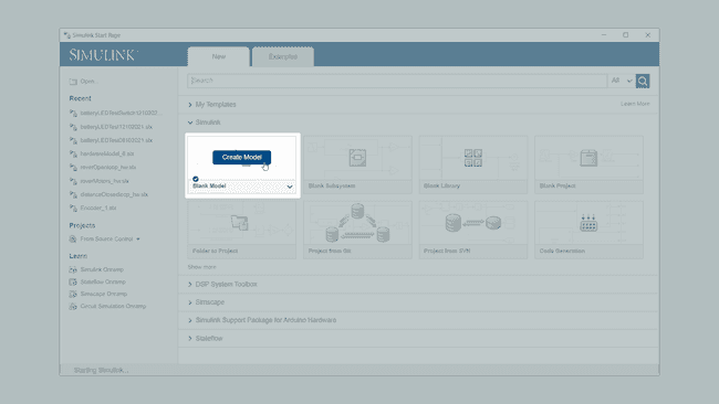
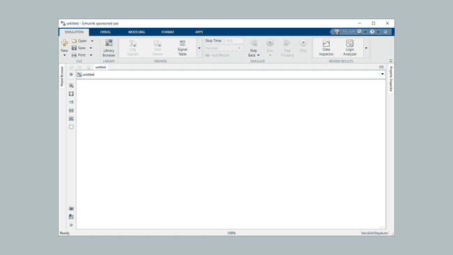
2. You will be greeted with the Simulink Start Page. Under Simulink, click on Blank Model to open up a new canvas.
3. A new window will pop up. In this Simulink window we will create the model, configure the simulation as well as upload to the Arduino board.
4. We can add blocks to do stuff, by selecting Library Browser from the Simulation ribbon. Under the Simulink Support Package for Arduino Hardware click on Common and add a Digital Output block. We will use this to control the LED on Pin 13.
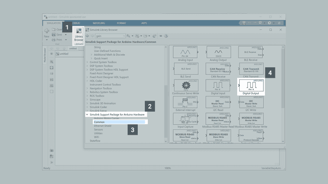
The easiest way to add a block to your canvas is to drag and drop it.
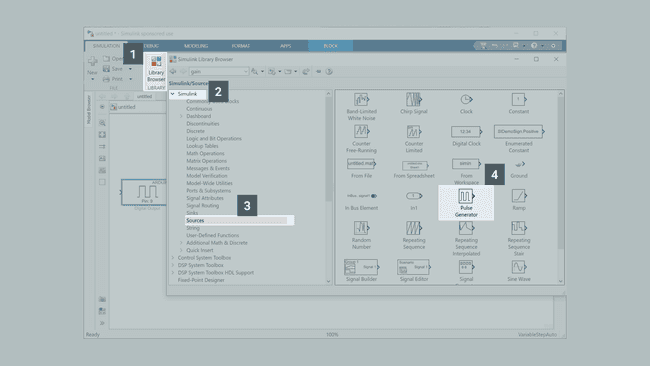
5. Go back to the Simulink Library Browser and under Simulink click on Sources. A list of different components that can act as sources, appear. Add the Pulse Generator block to you model. This block will help us generate the signal to turn the LED on and off.
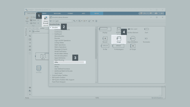
6. We will need one more component from the Simulink Library Browser. Under Simulink go to Sinks. Add the Scope block to your model. This will help us visualize the waveform generated.
7. We will now connect the blocks together. Click on the arrow to the right of the Pulse Generator block and drag it to the arrow on the left of the Digital Input block.
You can click and drag any of the blocks to move them around on the canvas. You can also use the scroll wheel to zoom in and out. In order to fit all of the blocks onto the display, hit Space.
8. We can see the transmitted signal by listening in with the Scope block. To do so, click on the arrow to the left of the Scope block and drag onto the link you previously created.
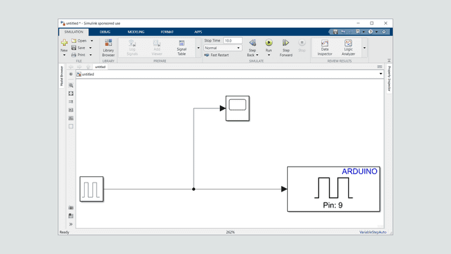
9. The blocks are now connected! However, before we continue we need to configure the Pulse Generator and Digital Output blocks. Let us start with the Digital Output block. You can see that by default the Pin is 9. However, as you know the LED is connected to Pin 13 on the Nano 33 IoT. Double click on this block to open up the properties and change Pin number to 13.
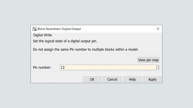
*You can see a list of possible Pin number values by clicking on View pin map.*
10. Now let us configure the Pulse Generator block. Double click on the Pulse Generator block to open up its Block Parameters. First, we will configure the Pulse type to be Sample based, since we are going to have a fixed time step. Set the Sample Time to be 0.2. This means that our model will operate in increments of one fifth of a second. An Amplitude of 1 is equivalent to a HIGH digital value for our model. Since we will define each Period to have 10 samples, then considering the Sample Time of 0.2 seconds, the duration of each period will be 2 seconds. The Pulse Width is defined as 5 samples. This will generate a periodic waveform, that turns on and off every one second.
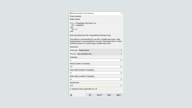
11. We can now run a simulation. In the Simulation ribbon set the Stop Time to 10 seconds then click on Run. After a few seconds the simulation should be complete.
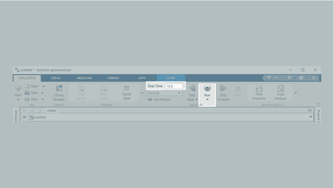
12. Double click on the Scope block. You should see a square wave with an amplitude of 1, a duty cycle of 50% and a period of 2.
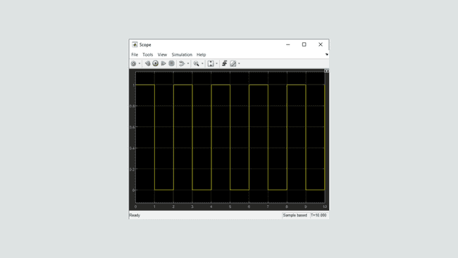
If your waveform is different or isn't shown, check the connection between the Scope and the Pulse Generator blocks. Make sure you have configured the Pulse Generator as we have done here.
13. Simulink also has the option to use Dashboard blocks to visualize the state of the LED. You can find these blocks in the Library Browser, under Simulink->Dashboard. For the purposes of this tutorial, click and drag the Lamp block to the canvas.
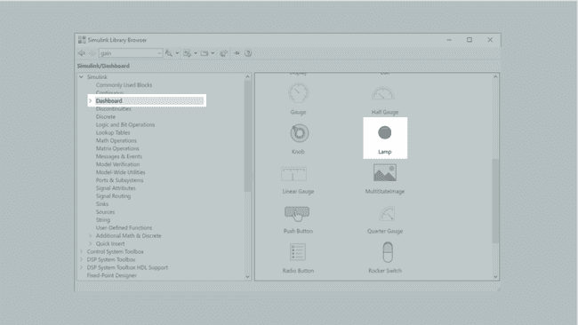
14. Dashboard blocks do not need to be connected via a signal link. Instead click on the 🔗 icon that appears when you hover over the Lamp block to open up Block Parameters window. Alternatively you can double click on the Lamp block, then click on the signal between the Pulse Generator and Digital Input blocks.
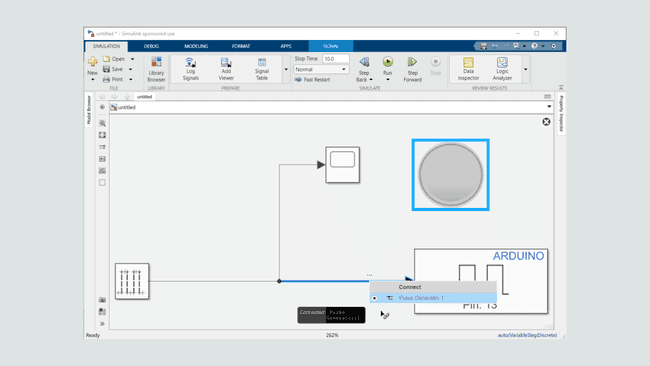
15. Try running the simulation again. You will notice that the Lamp block turns on and off very quickly. By default, the simulation runs as fast as your hardware will allow for. In order to enable a real-time simulation, click on the arrow underneath the Run button and then click on Simulation Pacing. In the window that opens up, enable the Enable pacing to slow down simulation checkbox.
16. Now click on Run. You will notice that a gauge has appeared next to the green play button, signalling that the Simulation Pacing has been enabled. The Lamp block will turn on and off every 1 second.
Control Nano 33 IoT LED From Within Simulink
1. We will now configure Simulink to access the hardware IO directly. This will allow you to directly control the LED on the Nano 33 IoT, from the model running in your computer.
2. Under the Modeling ribbon, click on the Model Settings button. This window gives us many options for configuring how the model itself is run including the solver configuration, default data types, diagnostic warnings/errors and the hardware implementation. For the purposes of this tutorial, we will change the hardware implementation to reflect our setup.
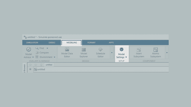
You can also press Ctrl + E to bring up the Model Settings window.
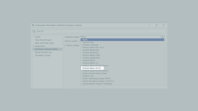
3. In the window that appears, under the Hardware board dropdown list select Arduino Nano 33 IoT. You will notice that the Device vendor and Device type items change to ARM Compatible and ARM Cortex respectively that reflects the microcontroller architecture of the Nano 33 IoT.
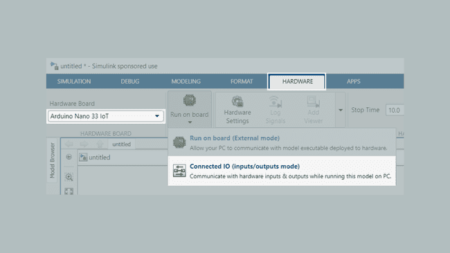
4. A new Hardware ribbon will appear. If configured correctly, under this ribbon, you will see Arduino Nano 33 IoT as the Hardware Board. In the Mode section, click on the downward facing arrow and select Connected IO.
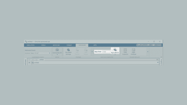
5. Make sure the Stop Time is set to 10, then click on Run with IO.
6. You should notice that the Lamp block on the LED of the Nano 33 IoT, both turn on 5 times in near unison with each other. Remember that in the Connected IO mode, Simulink is directly controlling Pin 13 on the Nano 33 IoT, and the board cannot operate in a standalone fashion. In the case that we want the program to operate in a standalone fashion, we need to deploy the model to the Nano 33 IoT by converting the model to microcontroller code and uploading it.
{/* Add a gif/video. /}
Try disconnecting the USB cable. You will see that the LED does not blink anymore.
Deploy to Nano 33 IoT for Standalone Operation
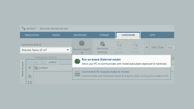
1. With the help of Simulink, we will enable standalone operation. In the Hardware ribbon, click on the downward arrow in the MODE section (from the previous section, it should be displaying Connected IO). Then choose Run on board (External Mode).
2. You will notice that the icons on the ribbon have changed slightly. To the far right, select Build, Deploy & Start.
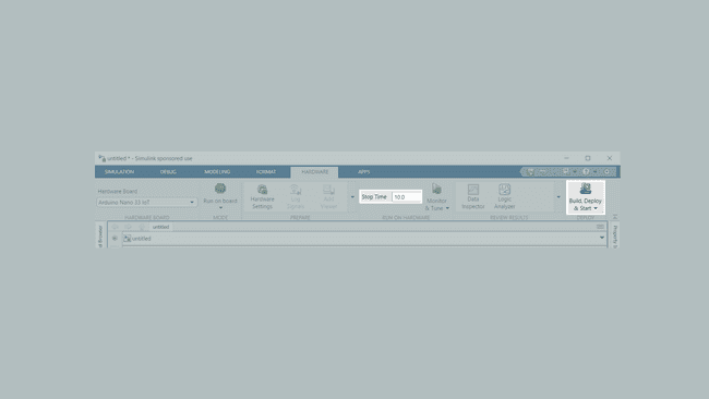
On R2021b and newer revisions of MATLAB, the default Simulink interface is over XCP. Compared to legacy serial, XCP provides higher stability. You can manually enabled this in older versions, or update to the latest version.
3. The Simulink model will be converted into microcontroller code, with the help of a MathWorks and Arduino libraries. This will take a few minutes, depending on the speed of your computer to complete.
4. The LED on you Nano 33 IoT will constantly blink. However, the Lamp block in your computer screen will not flash any more.
{/ Add a gif/video showing the Simulink model and the Nano Motor Carrier. /}
Try disconnecting the USB cable. Does the LED continue to blink?
Deploy to the Nano 33 IoT with Debug Capabilities
1. Now we are going to see how to compile code for the Nano 33 IoT, but keep the connection established to enable real-time debugging. This is very useful when adjusting control parameters such as the Proportional, integral and derivative gain used in PID (Proportional Integral Derivative) control. For now, we will see how to observe the battery levels of the Nano Motor Carrier.
2. From the Simulation ribbon, open up the Library Browser. Scroll down to Simulink Support Package for Arduino Hardware and in the Arduino Motor Carrier subcategory add the Battery Read block to your model.
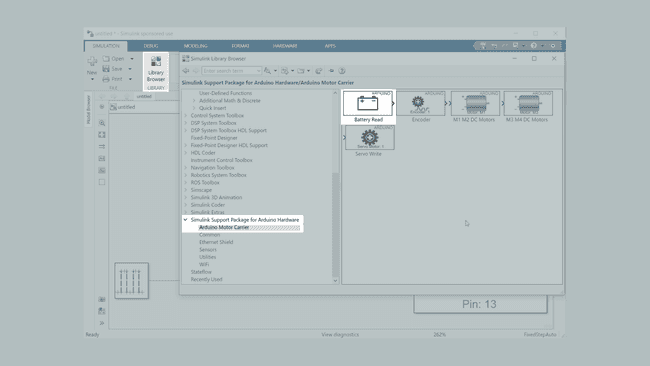
3. The Battery Read block gives the voltage as an integer between 0 to 4095. To convert this raw value into voltage, we will need to multiple it by 12/4095. To do so we can get the help of a Gain block. Go up to the Simulink section and under Commonly Used Blocks add the Gain block to your model.
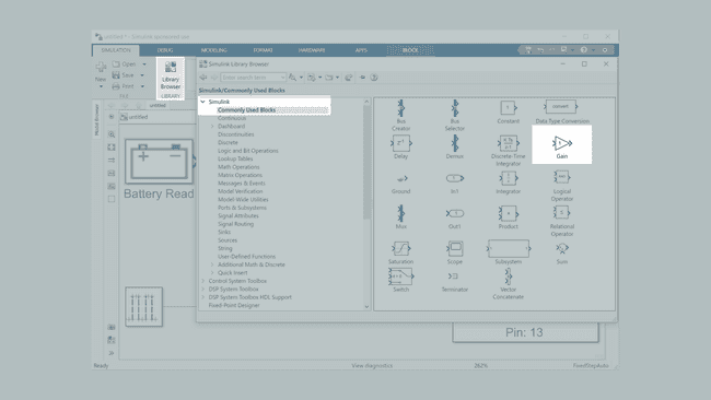
*The Battery Read block provides a 12-bit value that is obtained from the ADC on the Nano Motor Carrier. The maximum value (4095) represents a voltage of 12V. The Gain block is used to convert the ADC value to a human-readable voltage.*
4. Now we need a way to display this value. In the Simulink category, under the Sinks subsection, find and add the Display block; this will allow us to see the values.
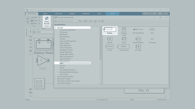
5. We will now create a path from the Battery Read to the Gain Block and then the Display Block.
To create a signal link, click and drag from an outgoing arrow to the incoming arrow on the destination block.
6. In order to configure the gain block, double click and enter 1/236 as the Gain. In the Signal Attributes tab, change the Output data type to
double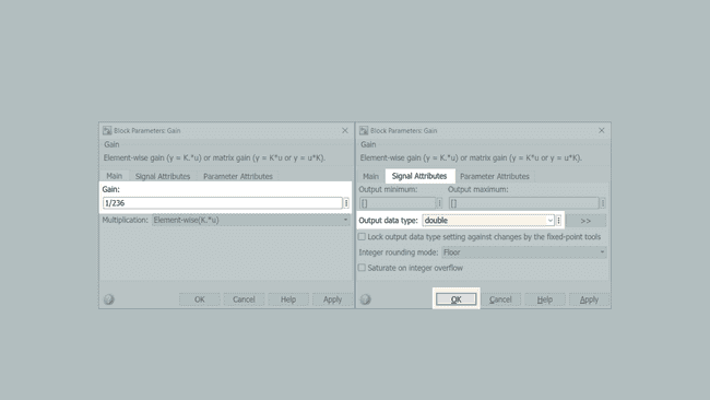
7. Go to the Hardware ribbon. Make sure that the Mode is set to Run on board and that the Stop Time is set to 10. Click on Monitor and Tune. You should see the value on the Display block correspond to the voltage of the battery.
{/ Add a gif/video. /}
Using Wi-Fi
1. Open up the Hardware Settings from the Hardware Ribbon. In the Hardware Implementation tab, under the Target hardware resources click on External mode then choose
XCP on WiFi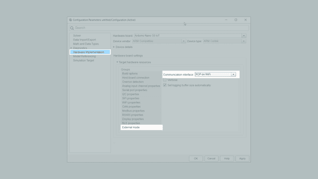
For the purposes of this tutorial, we will leave the
box unchecked. This means that a dynamic IP address will be allocated to the Nano 33 IoT.Use static IP address and disable DHCP
2. We now need to configure the wireless settings. Click on Wi-Fi properties and enter the Service set identifier (SSID) or name of your wireless network. Select the appropriate encryption (
NoneWEPWPA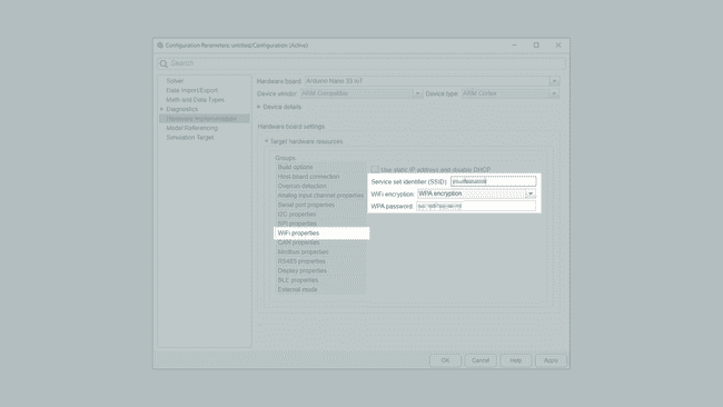
Some school and corporate networks may require login credentials which is not supported at the moment. In this case, contact your network administrator. Alternatively, you can use a wireless hotspot on your phone.
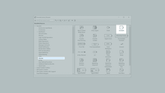
3. Let us try and add a switch so that we can control the LED wirelessly via Simulink. From the Simulink Library Browser, under Simulink->Signal Routing->Sources add the Manual Switch to the model. Also add the Constant block from the Sources group.
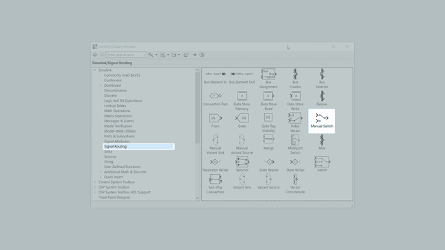
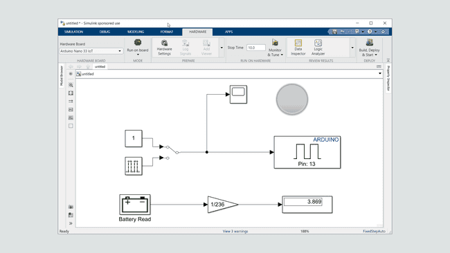
4. Add the Manual Switch block to the model as seen in the image below, between the Pulse Generator and Digital Output block. One signal will go from the Constant block that we added, and the other from the Pulse Generator block we had before as input to the Manual Switch block. Make sure that the Lamp block is connected to the signal after the Manual Switch.
5. Double click on the Constant block and change the Constant value to
0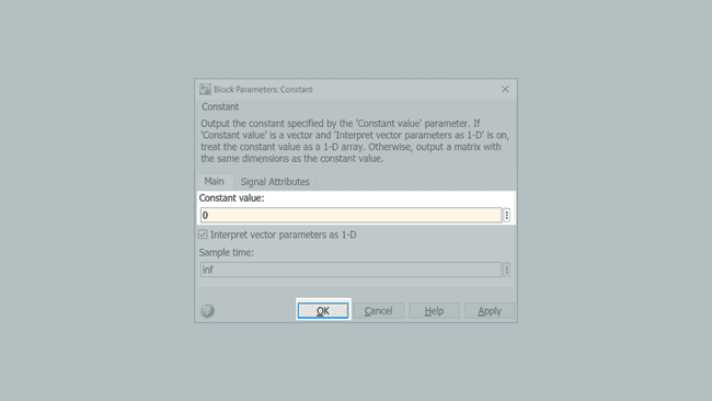
6. Click OK and then click on Monitor & Tune. Simulink will now compile the model and upload it to the board.
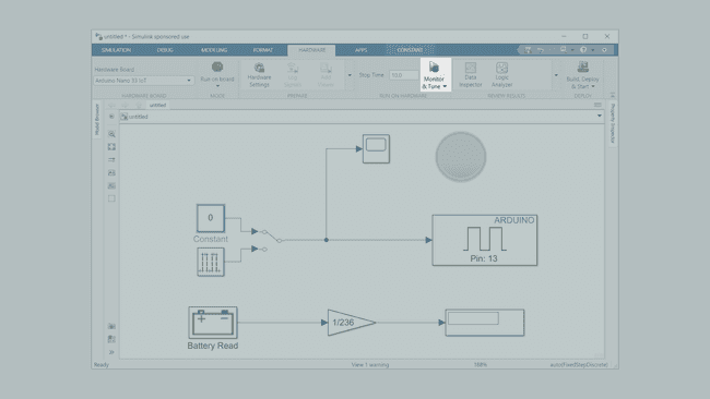
7. Once uploaded and the Wi-Fi connection is established you will see Running the model on Arduino Nano 33 IoT.... After this step is complete, you can disconnect the USB cable. You should see that the battery voltage is still displayed in real time.
8. Double click on the Manual switch block. You will see the state of the LED change from blinking to off.
{/ Add a gif/video. /}
Conclusion
Now that you have gone through this tutorial, you now know how to use Simulink to control the Nano Motor Carrier with the help of the Nano 33 IoT. You learnt how to create a model, by connecting together Blocks and to then simulate it in your computer. Using Connected IO you can control your Arduino board connected by a USB cable. Through external mode, you can run deploy the model to your board to run independently (Build, Start and Deploy) or keep the connection established with your computer (Monitor & Tune). In addition to USB, you can also control the Arduino Nano Motor Carrier over Wi-Fi thanks to the wireless capabilities of the Nano 33 IoT.
Simulink together with the Arduino platform opens up possibilities for rapid testing of concepts and ideas both in software as well as in hardware. The different operations modes allow you to choose the most suitable approach to your problem.
Troubleshooting
- Make sure to not use blocks in a multirate configuration.
- Connected IO mode has limited compatibility with the Arduino Simulink blocks. Try using External Mode for improved simulation capabilities.
- Wi-Fi mode only works for External Mode (either Monitor & Tune or Build, Start and Deploy).
- Ensure that
orXCP on Serial
is selected as the Communication Interface. Compared to legacy Serial, XCP provides additional functionality and stability.XCP on Wi-Fi - Make sure that the USB Cable is connected. For the Wi-Fi approach demonstrated in this tutorial, we will need to have the USB connected when the code is being uploaded.
Further Ideas
- Try changing the Pulse Generator duty cycle and frequency.
- In the Connected IO or Monitor & Tune configuration, try using a Slider dashboard element block to change the
parameter during operation. See the MathWorks documentation for more information about this Simulink block.Pulse Generator:PulseWidth - In addition to including all the software and hardware components needed to complete this tutorial, the Arduino Engineering Kit Rev 2 includes a specially curated experience to learn about the Simulink-Arduino interface, through three exciting projects in a hands-on manner.
- Read up more about Connected I/O and its use with Arduino blocks or watch this webinar provided by MathWorks.
Suggest changes
The content on docs.arduino.cc is facilitated through a public GitHub repository. If you see anything wrong, you can edit this page here.
License
The Arduino documentation is licensed under the Creative Commons Attribution-Share Alike 4.0 license.