Portenta H7 as a Wi-Fi Access Point
In this tutorial you will configure the Portenta H7 as an access point and build a simple web server that will allow you to control the built-in RGB LEDs from your mobile device.
Overview
Portenta H7 comes with an on-board Wi-Fi and a Bluetooth® Module that allows to develop IoT applications that require wireless connectivity and Internet access. Turning the board into an access point allows to create a Wi-Fi network on its own and allows other devices to connect to it. In this tutorial you will learn to set up your board as an access point web server and remotely control the red, green and blue LEDs on the built-in RGB LED by accessing an HTML page on your mobile device’s browser.
Goals
- About the built-in Wi-Fi + Bluetooth® module.
- How a client-server model works
- How to create an HTTP communication channel between the board and an external device.
Required Hardware and Software
- Portenta H7 (ABX00042) or Portenta H7 Lite Connected (ABX00046)
- One USB-C® cable (either USB-A to USB-C® or USB-C® to USB-C®)
- Arduino IDE 1.8.10+ or Arduino Pro IDE 0.0.4 +
- A smart phone
Access Point Configuration
The Portenta H7 features a Murata 1DX, which is a high performance chipset which supports Wi-Fi 802.11b/g/n + Bluetooth® 5.1 BR/EDR/LE, up to 65 Mbps PHY data rate on Wi-Fi and 3 Mbps PHY data rate on Bluetooth®. This module helps to configure the Portenta into three different modes of operation - an Access Point, a Station, or both. In this tutorial we will only focus on the access point configuration.
When the board is configured to operate as an access point, it can create its own wireless LAN (WLAN) network. In this mode, the board transmits and receives signals at 2.4 GHz allowing other electronic devices with Wi-Fi capabilities using the same bandwidth to connect to the board.
With the access point set up, you create a client server architecture where the board provides a web server communicating with the client devices over HTTP. The connected devices can then make HTTP GET requests to the server to retrieve web pages served by the web server on the board. This makes the Portenta H7 an ideal board for developing IoT solutions where external client devices can send and receive information while more complex processing tasks take place on the server.
Instructions
Setting Up the Web Server
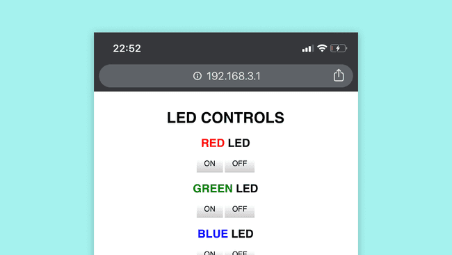
In this tutorial you are going to convert the board into an access point and use it to set up a web server which provides a HTML webpage. This page contains buttons to toggle the red, green and blue color of the built-in LED. You will then connect your mobile device to this access point and access this web page through the browser on your mobile phone. Once retrieved, you will be able to control the state of the red, green and blue LED on the built-in RGB LED from your mobile device.
1. The Basic Setup
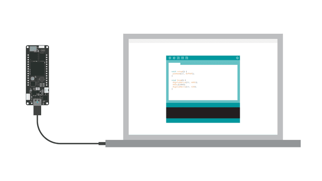
Begin by plugging in your Portenta board to your computer using a USB-C® cable and open the Arduino IDE. If this is your first time running Arduino sketch files on the board, we suggest you check out how to set up the Portenta H7 for Arduino before you proceed.
2. Create the Web Server Sketch
Next you need to create a web server sketch that will handle the HTTP GET requests and provide the client devices with the HTML web page. The Wi-Fi library provides all necessary methods that allows Arduino boards to use their Wi-Fi features provided by the on-board Wi-Fi module. To set up the web server copy the following code, paste it into a new sketch file and name it SimpleWebServer.ino.
Note: You can access the final sketch inside the library: Examples > Arduino_Pro_Tutorials > Portenta H7 as a Wi-Fi Access Point > SimpleWebServer
1#include <WiFi.h>2#include "arduino_secrets.h"3
4///////please enter your sensitive data in the Secret tab/arduino_secrets.h5char ssid[] = SECRET_SSID; // your network SSID (name)6char pass[] = SECRET_PASS; // your network password (use for WPA, or use as key for WEP)7int keyIndex = 0; // your network key Index number (needed only for WEP)8
9int status = WL_IDLE_STATUS;10
11WiFiServer server(80);12
13void setup() {14 // put your setup code here, to run once:15 Serial.begin(9600);16 while (!Serial) {17 ; // wait for serial port to connect. Needed for native USB port only18 }19 20 Serial.println("Access Point Web Server");21
22 pinMode(LEDR,OUTPUT);23 pinMode(LEDG,OUTPUT);24 pinMode(LEDB,OUTPUT); 25
26 // by default the local IP address of will be 192.168.3.127 // you can override it with the following:28 // WiFi.config(IPAddress(10, 0, 0, 1));29
30 if(strlen(pass) < 8){ 31 Serial.println("Creating access point failed");32 Serial.println("The Wi-Fi password must be at least 8 characters long");33 // don't continue34 while(true);35 }36 37 // print the network name (SSID);38 Serial.print("Creating access point named: ");39 Serial.println(ssid);40
41 //Create the Access point42 status = WiFi.beginAP(ssid,pass);43 if(status != WL_AP_LISTENING){44 Serial.println("Creating access point failed");45 // don't continue46 while (true);47 }48
49 // wait 10 seconds for connection:50 delay(10000);51
52 // start the web server on port 8053 server.begin();54
55 // you're connected now, so print out the status56 printWiFiStatus();57 58}59
60void loop() {61
62 // compare the previous status to the current status63 if (status != WiFi.status()) {64 // it has changed update the variable65 status = WiFi.status();66
67 if (status == WL_AP_CONNECTED) {68 // a device has connected to the AP69 Serial.println("Device connected to AP");70 } else {71 // a device has disconnected from the AP, and we are back in listening mode72 Serial.println("Device disconnected from AP");73 }74 }75
76 WiFiClient client = server.available(); // listen for incoming clients77
78 if (client) { // if you get a client,79 Serial.println("new client"); // print a message out the serial port80 String currentLine = ""; // make a String to hold incoming data from the client81 82 while (client.connected()) { // loop while the client's connected83 84 if (client.available()) { // if there's bytes to read from the client,85 char c = client.read(); // read a byte, then86 Serial.write(c); // print it out the serial monitor87 if (c == '\n') { // if the byte is a newline character88
89 // if the current line is blank, you got two newline characters in a row.90 // that's the end of the client HTTP request, so send a response:91 if (currentLine.length() == 0) {92 // HTTP headers always start with a response code (e.g. HTTP/1.1 200 OK)93 // and a content-type so the client knows what's coming, then a blank line:94 client.println("HTTP/1.1 200 OK");95 client.println("Content-type:text/html");96 client.println();97
98 // the content of the HTTP response follows the header:99 client.print("<html><head>");100 client.print("<style>");101 client.print("* { font-family: sans-serif;}");102 client.print("body { padding: 2em; font-size: 2em; text-align: center;}"); 103 client.print("a { -webkit-appearance: button;-moz-appearance: button;appearance: button;text-decoration: none;color: initial; padding: 25px;} #red{color:red;} #green{color:green;} #blue{color:blue;}");104 client.print("</style></head>");105 client.print("<body><h1> LED CONTROLS </h1>");106 client.print("<h2><span id=\"red\">RED </span> LED </h2>");107 client.print("<a href=\"/Hr\">ON</a> <a href=\"/Lr\">OFF</a>");108 client.print("<h2> <span id=\"green\">GREEN</span> LED </h2>");109 client.print("<a href=\"/Hg\">ON</a> <a href=\"/Lg\">OFF</a>");110 client.print("<h2> <span id=\"blue\">BLUE</span> LED </h2>");111 client.print("<a href=\"/Hb\">ON</a> <a href=\"/Lb\">OFF</a>");112 client.print("</body></html>");113
114 // The HTTP response ends with another blank line:115 client.println();116 // break out of the while loop:117 break;118 } else { // if you got a newline, then clear currentLine:119 currentLine = "";120 }121 } else if (c != '\r') { // if you got anything else but a carriage return character,122 currentLine += c; // add it to the end of the currentLine123 }124
125 // Check to see if the client request was "GET /H" or "GET /L":126 if (currentLine.endsWith("GET /Hr")) {127 digitalWrite(LEDR, LOW); // GET /Hr turns the Red LED on128 }129 if (currentLine.endsWith("GET /Lr")) {130 digitalWrite(LEDR, HIGH); // GET /Lr turns the Red LED off131 }132 if (currentLine.endsWith("GET /Hg")){133 digitalWrite(LEDG, LOW); // GET /Hg turns the Green LED on134 }135 if (currentLine.endsWith("GET /Lg")){136 digitalWrite(LEDG, HIGH); // GET /Hg turns the Green LED on137 }138 if (currentLine.endsWith("GET /Hb")){139 digitalWrite(LEDB, LOW); // GET /Hg turns the Green LED on140 }141 if (currentLine.endsWith("GET /Lb")){142 digitalWrite(LEDB, HIGH); // GET /Hg turns the Green LED on143 } 144 145 }146 }147 // close the connection:148 client.stop();149 Serial.println("client disconnected");150 }151 152}153
154void printWiFiStatus() {155 // print the SSID of the network you're attached to:156 Serial.print("SSID: ");157 Serial.println(WiFi.SSID());158
159 // print your Wi-Fi shield's IP address:160 IPAddress ip = WiFi.localIP();161 Serial.print("IP Address: ");162 Serial.println(ip);163
164 // print where to go in a browser:165 Serial.print("To see this page in action, open a browser to http://");166 Serial.println(ip);167}This sketch describes how the server will handle an incoming HTTP GET request from a client, both to request the HTML web page from the server and the requests to change the LED states using dedicated URLs.
Here the web page is just a simple HTML page with buttons to toggle the LED states. The way in which the web page works is: whenever a button on the web page is pressed, the client device (in this case your phone) sends a HTTP GET request to a URL denoted by a letter, in this case H or L (H stands for HIGH, L stands for LOW) followed by the LED color that should be turned on or off r, g or b. For example, to turn on the red LED the URL is /Hr . Once the server receives this request, it changes the corresponding LED state, closes the connection and continues to listen to next requests.
Remember that the built-in RGB LEDs on the Portenta H7 need to be pulled to ground to make them light up. This means that a voltage level of LOW on each of their pins will turn the specific color of the LED on, a voltage level of HIGH will turn them off.
3. Create the arduino_secrets.h Tab
A good practice is to have sensitive data like the SSID and the password required to identify and connect to a certain network within a separate file. Click on the arrow icon below the Serial Monitor button and open a new tab in the Arduino IDE. This will create a new file.
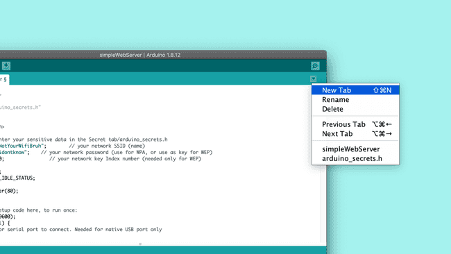
Name the file arduino_secrets.h and click OK.
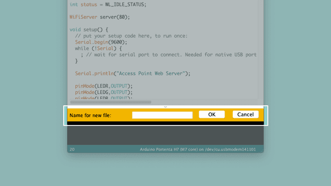
Once you have created the new tab, you will see an empty page in the IDE. Define two constants
SECRET_SSIDSECRET_PASS1# define SECRET_SSID "PortentaAccessPoint"2# define SECRET_PASS "123Qwerty"The SSID (PortentaAccessPoint) and password (123Qwerty) are placeholder strings made for this tutorial. For security reasons you should rename them to something memorable but not easy to guess. Keep in mind that the password must be at least 8 characters long.
In order to access the
SECRET_SSIDSECRET_PASS1# include “arduino_secrets.h”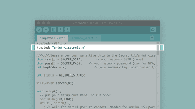
4. Upload the Code
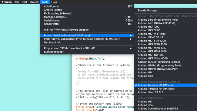
Select the Arduino Portenta H7 (M7 core) from the Board menu and the port the Portenta is connected to. Upload the simpleWebServer.ino sketch. Doing so will automatically compile the sketch beforehand.
Once you have uploaded the code, open the Serial Monitor. You will be able to see the IP address of the access point. You will also see the message,
Device disconnected from AP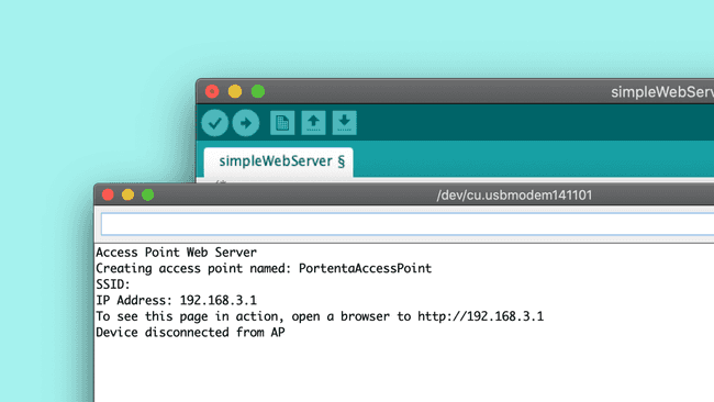
5. Connecting to the Portenta Access Point
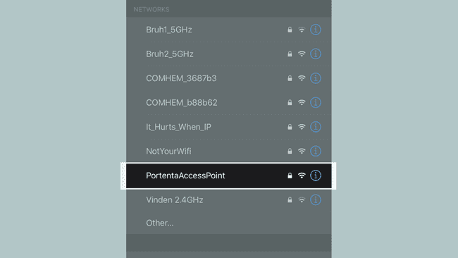
Once the access point is active and ready to be connected with external devices, you will be able to find the PortentaAccessPoint on the list of networks on your mobile device. Once you have entered the password you have defined earlier, your smart phone will connect to access point.
Now open a browser window on your mobile device and copy & paste the URL containing Portenta’s IP address that is displayed on the serial monitor.
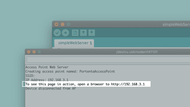
Once you have entered the URL, the client sends a GET request to the web server to fetch the HTML web page specified in the code. Once loaded, you will see the web page in your mobile browser.
6. Access the Board From Your Mobile Device
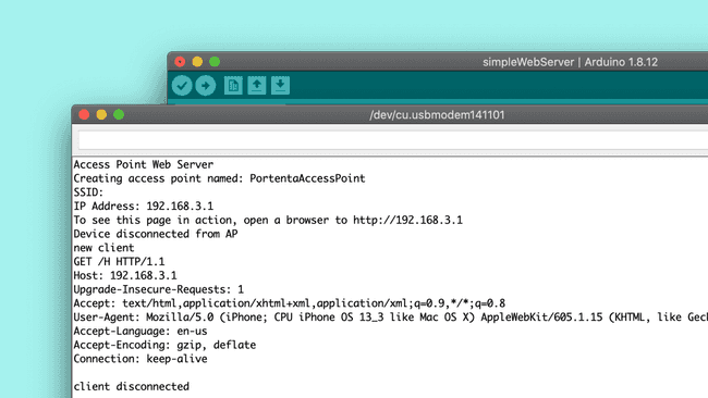
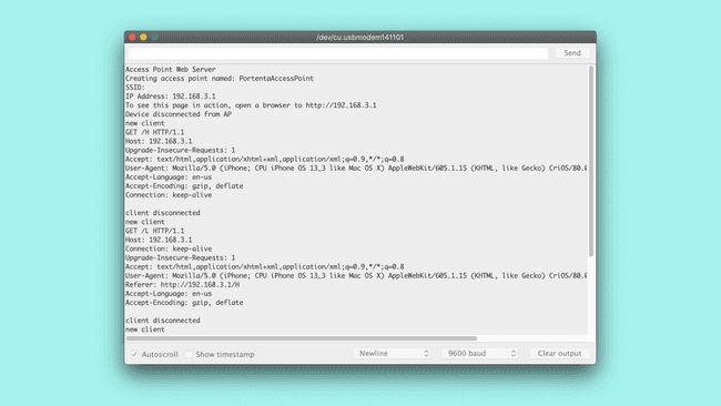
If you take a look at the Serial Monitor, you can see the details of the HTTP GET request and other details of the device connected to the access point. The GET request is always in the following format:
1GET URL HTTP/1.1The URL is a string of characters sent to the server, in this case /Hx (where x stands for the color of the LED). This request containing the URL is received on the server and it replies with the following HTTP/1.1 response indicating that the connection was successful:
1HTTP/1.1 200 OKOnce the server has responded to this request, it closes the connection and continues listening to next GET requests.
You are now be able to toggle the states of the red, green and blue LED through the buttons displayed on your mobile browser. Every time you press a button, the client sends a GET request to a URL in the format /Hx or /Lx ,where x can be ‘r’, ‘g’ or ‘b’, depending on the button pressed on the HTML page. The web server then reads the URL requested by the client, changes the state of the LED corresponding to the URL and closes the connection.
Conclusion
This tutorial shows one of the several capabilities of the on-board WiFi+Bluetooth® module by configuring the board as an access point and setting up a web server. You have also learnt how a simple client-server model and the underlying HTTP requests and responses work.
Next Steps
Now that you have learnt how to set up a board as an access point and understand the client-server model, start experimenting with the simpleWebServer.ino sketch. This sketch can be tweaked in a variety of ways based on your needs. For example, you can add a slider to the HTML page that changes the blink rate of the built-in RGB LED from your mobile device.
Suggest changes
The content on docs.arduino.cc is facilitated through a public GitHub repository. If you see anything wrong, you can edit this page here.
License
The Arduino documentation is licensed under the Creative Commons Attribution-Share Alike 4.0 license.